


Magnetic Particles Testing (MT) is effective in locating surface or near-surface discontinuities of ferromagnetic materials. It is most commonly used to evaluate weld joint surfaces, intermediate checks of weld layers, and back-gouged surfaces of completed welds. Typical types of discontinuities that can be detected using MT, with adequate accessibility, include cracks, lamination, laps, and seams.
In this method, the weld (and HAZ) is locally magnetized, creating a magnetic field in the material. Finely divided ferromagnetic particles are then applied to the magnetized surface and are drawn to breaks in the magnetic field (causing the formation of north and south poles at the imperfection) resulting from discontinuities, as shown in Figure 1 and Figure 2.
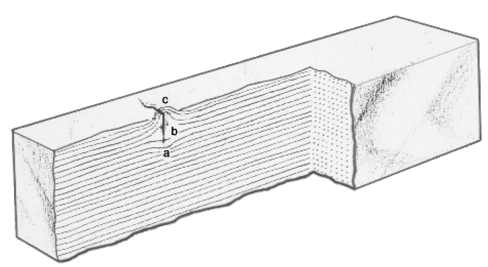
Figure 1—Surface-Breaking Discontinuity
Figure 1 shows the disruption to the magnetic field caused by a defect open to the surface. Ferromagnetic particles are drawn to the break in the flux field, creating north and south poles. The pattern of the particles may be very sharp and distinct, or diffuse, depending upon several factors including field strength, type of imperfection, and indicator medium
Figure 2—Subsurface Discontinuity
Figure 2 illustrates how a subsurface defect would also disrupt the magnetic lines of flux. The observed indication would not be as clearly defined as would a defect open to the surface.
The pattern formed by the particles represents the shape and size of any existing discontinuities, as seen in Figure 3. The particles used during the exam can be either dry or wet, depending upon the type of
imperfection being examined and the level of sensitivity required. If the examination is performed in normal lighting, the color of the particles (known as the color-contrast method) should provide adequate contrast to the exam surface. The best results are achieved when the lines of flux are perpendicular to the discontinuity. The inspections should overlap by at least 50 mm (2 in.). Two inspections are typically performed, one parallel to the weld and one perpendicular the weld, to provide the maximum probability of coverage. When a magnetic force is applied to the material, a magnetic flux field is created around and through the material. Discontinuities that are perpendicular to the lines of flux attract the magnetic particles, causing an indication as shown in Figure 4.

Figure 3—Weld Discontinuity

Figure 4—Flux Lines
Figure 5 illustrates the setup for detecting transverse indications. The yoke is placed parallel on the weld to detect discontinuities transverse to the weld. Figure 6 shows the setup for detecting indications that run parallel to the weld. In this case, the yoke is placed across the weld to detect discontinuities parallel to the weld. Imperfections will need to be perpendicular to the magnetic flux field for maximum probability of detection.
For added sensitivity, wet fluorescent magnetic particle (WFMT) techniques may be used. With this technique, a filtered blacklight is used to observe the particles, which requires the examination area to be darkened as specified in ASME Section V, Article 7.
ASME Section V, Article 7, lists requirements for MT. Some codes and specifications may list compliance with these requirements as being mandatory. ASME B31.3 and ASME Section VIII, Division 1, requires MT to be performed in accordance with Article 7. Some of the requirements listed in this article include:
- examination procedure information;
- use of a continuous particle application method;
- use of one of five magnetization techniques;
- required calibration of equipment;
- two examinations perpendicular to each other;
- maximum surface temperature for examination;
- magnetization currents;
- evaluation of indications in terms of the acceptance standards of the referencing code;
- demagnetization;
- minimum required surface illumination (visible or blacklight) of the part under examination.

Figure 5—Detecting Discontinuities Transverse to Weld


0 Comments